

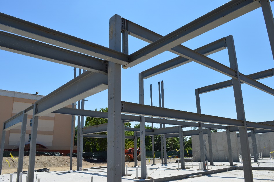
Have you ever tightened a bolt? How tight is tight enough? Is it possible to tighten it too much? Whereas these questions might not matter as much when you assemble an IKEA side table for your living room, they sure do matter when you are tightening bolts in a member connection for a steel building. One convention is to follow the “snug-tight” method where bolts are tightened until first sign of resistance and then given another quarter turn.
Another convention is to use direct tension indicators. Direct tension indicators are washers that have small protrusions on them. When the bolt is tightened, the gap between the unturned element and the washer decreases. The size of the gap is then measured and when it reaches the desired size, the bolt is pronounced tightened. It is often required to have all the connections in a building inspected to ensure tightened adequacy. But to go and climb up to every connection and hand check each bolt is both extremely time consuming and still subject to human error, especially when there are a lot of connections and thus a lot of bolts to inspect.
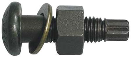
Then a special machine is used to tighten the nut without turning the bolt. But here is where the ingenious part of the design comes in. When it has been tightened to the required torque, the small spline pops off! So that is when you know that the bolt is tightened just right and, as an added bonus, it makes for a very quick, easy, and thus efficient connection inspection, you just have to look for all the bolts to have their splines popped off.
Snug-tight conditions and direct tension indicators are still widely used today, so tension control bolts are just another option to use in construction, but a pretty innovative option!
 |
 |
 |
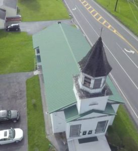
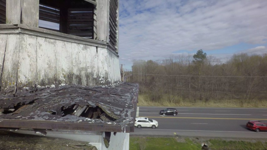
Aerial Image taken with NKB’s UAV
Documenting existing conditions can often times be difficult for Architects & Engineers, because the conditions are concealed, too high, out of reach, or outright unsafe to get to. The question is, how can you see things that you cannot ordinarily see? Technology. Using technology to your advantage is the way you get the job done.
When posed with performing a condition assessment and preparing the design for the restoration of the steeple on the historic St. Mary’s Anglican Church in Liverpool, NY, NKB offered the use of our unmanned aerial vehicle (UAV) with an onboard high definition digital camera to document the conditions that were otherwise unobservable from the ground. The conditions were too high and unsafe to try to get to with a ladder or lift. By using our UAV, NKB could provide high definition still or video imagery of conditions on the steeple that the owner, design professional, and contractor could not otherwise see. Having this visual documentation of an otherwise obscured condition is allowing the design team and the contractor to proceed with the design and construction activities on the steeple in an orderly manner.
The next big thing in Architecture and Engineering is not necessarily some earth-shaking new approach to re-invent the built environment. The next big thing is how we as design professionals can use technology in creative ways to provide unparalleled service for our clients.
Using technology in creative ways to work for you.
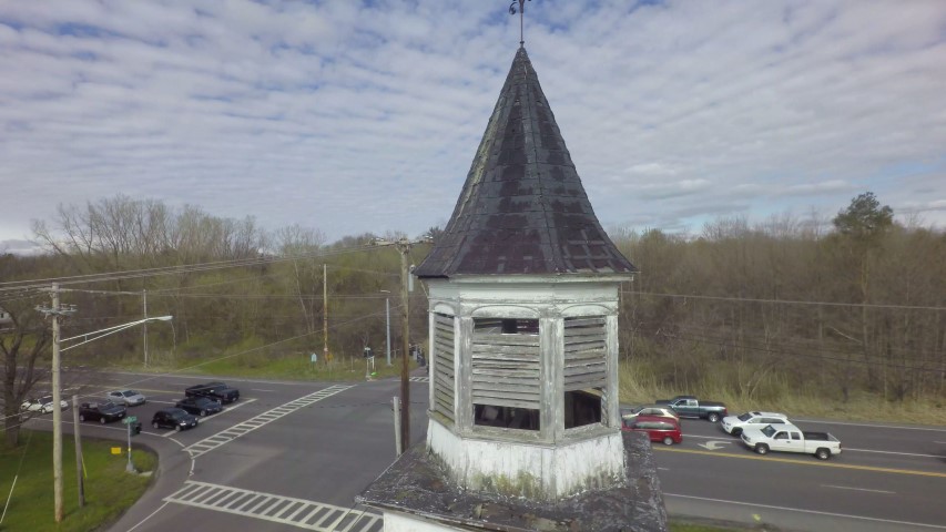
Aerial Image taken with NKB’s UAV
Up close on a hard to reach spot using NKB’s UAV
Recently, NKB was called by an existing client to assist them with a problem they began experiencing with ice falling from window sills several stories above the ground. In mid-January, Old Man Winter comes to Upstate New York and dropped 14 inches of snow in about 36 hours. Temperatures ranged from 15ºF to 25ºF and wind speeds were consistently between 5 and 15 mph with occasional gusts of up to 35-40mph. Over the two days which followed the completion of the storm there were reports of ice buildup and falling to grade below. The client called us in to examine what might be causing the ice build-up. What we found when we walked the perimeter of the building and looked out on various façades of the building from facing windows was very telling.
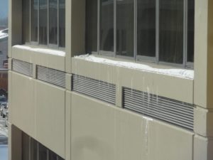
Melting at Window Sills
Each window sill showed some snow and ice still in place near the edge of the sill. The 6-8 inches nearest to the window was clear in all locations. Every – Single – Window. All 245 instances, showed the same clear area adjacent to the windows with ice buildup at the edge. Our client admitted that they did not recall if this was a problem prior to the façade renovation project. It had been several years since pedestrians were allowed anywhere near the building so there was no institutional memory of occurrences like this happening previously.
We began running through the list of things that could possibly cause this melting condition:
1. The windows are known to be headaches to the building management. Infiltration problems are known to exist so could we be getting warm air leakage at the windows causing snow melt? Well, warm air leakage would likely be a less uniform condition. Coupled with the fact that the façade renovation project that was just completed included the resealing of the entire perimeter of each of the windows, we decided that this was not a major contributor.
2. Since this is a horizontal surface, it could be that the sun was causing the snow melt, right? When we noticed that the condition existed at all faces, regardless of orientation (including the north facing façade which gets essentially zero sun at this time of year), we ruled out solar melting as a primary contributor to the problem.
3. Upon a closer inspection of the window sills and a reexamination of the original construction documents from the 1970’s, we realized that this pre-cast concrete window sill was likely acting as a thermal short. It extended, unbroken, from the exterior to the interior of the building.
A thermal short is a condition in which thermal energy is allowed to flow along a path of least resistance from a heat source to a colder region on the other side of the barrier. Consider an electrical short circuit. An electrical short is one in which the electricity is allowed to flow along a shorter path than intended and in doing so damages components and ceases to work properly (hopefully without killing anyone in the process). A thermal short is a similar phenomenon. In most homes the walls contain some form of insulation to provide greater resistance to heat loss in the winter or air conditioning in the summer. In a commercial building, a thermal short is most often exterior panels supported by metal clips and brackets which are tied to metal structural components. This string of metal tied to metal creates an easy path along which thermal energy can flow. This building did not have an unbroken string of metal from exterior to interior making identification of a thermal short in this case particularly difficult. However, the uninsulated concrete still served the function of a thermal short by acting as a path of least resistance for the thermal energy in the building to escape.
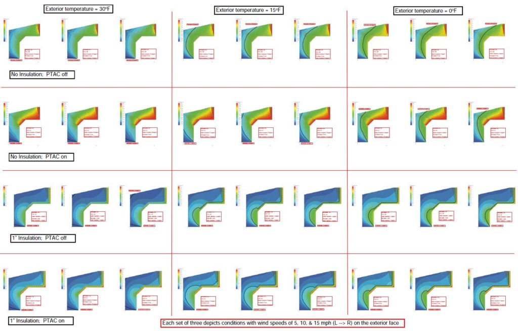
Most people consider concrete to be of sufficient thermal mass and to be a relatively capable thermal insulator. Compared to metal window frames and door frames or z-channel, this understanding is exactly right. Compared to air gaps and closed-cell insulation, this is an error in judgement. In an effort to better explain what was causing the observed conditions and to predict a likely solution we put together, a Finite Element Analysis (FEA) thermal model of the window sill conditions. We created 50 different runs with a varying set of boundary conditions and thermal loads. These runs examined the following conditions:
| Variable | Values |
| Insulation in PTAC cavity | Yes/No |
| PTAC operational | Yes/No |
| Exterior Temperature | 30º/15º/0º F |
| Wind Speed Across Face of Building | 5/10/15 mph |
What came out of the simulations was both expected and surprising at the same time. The results of the model with the existing conditions as inputs produced outputs which would predict the melting and refreezing conditions exactly as observed.
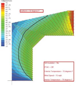 Existing condition |
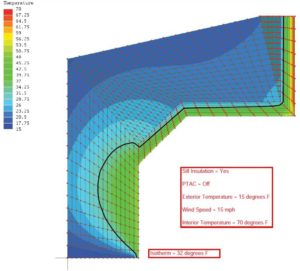 Proposed condition |
We then created a series of simulations in which we insulated the interior faces of the concrete so as to attempt to create the thermal break required to prevent the wholesale loss of building heat through the concrete sill. The results of these simulations predict that 1 inch of polyisocyanurate insulation on the interior face of the concrete sill will prevent melting on the sill in all conditions except those which also do not allow the snow melt to refreeze on the concrete.
Over the remaining winter months, we have found that this condition seemed to be limited to larger snow events. We had several smaller snow falls (less than 4 inches at a time) and it seems that there is a critical mass of snow which is required to create the pieces of ice that are large enough to separate from the building. This critical mass has not been reached since that snow storm in mid-January but considering that we, in Syracuse, routinely win the Golden Snowball award for largest snowfall total during the winter months, we can be assured that we will typically get at least one storm capable of creating the conditions to cause this occurrence each year. The implementation of the findings of this analysis is yet to be completed and will be the topic of ongoing discussion with the client.
So what is the moral of this story? Thermal energy is a slippery devil. It finds unexpected paths and causes unexpected consequences. Thermal shorts in all of their forms can be a significant building performance and energy consumption issue. These issues impact not only the long term performance of the building itself, but the people who use the building day-in-and-day-out. This case study serves to highlight the usefulness of a relatively straight-forward Finite Element Analysis steady state thermal model in helping to determine the causes of a given condition as well as helping to identify what recommendations we can make in order to best address them.
Scott Girouard – Spring Intern 2016
The opportunity to work simultaneously alongside architects and engineers was something I knew I wanted as I entered Syracuse University. I enjoyed seeing the two disciplines build off one another in a responsive manner.
For this reason, I chose to major in Civil Engineering and minor in Architecture. This unique, yet practical degree combination further interested me in how closely the two disciplines could function with respect to one another.
An opportunity to work collaboratively or simultaneously with engineers and architects had managed to elude me even as I entered my senior year. Unsuccessful previous attempts included working on a student architectural competition team, a design-build project, and inquiring about research pertaining to engineering and architecture collaboration efforts.
My internship at NKB came as I shifted my focus to design opportunities outside of SU. Upon my first glimpse of the NKB office I knew I was in the right place. The mostly open space allows me to easily ask engineers and architects any questions I may have.
What I did not know going into NKB was the range of exciting building types that I would soon be exposed to. NKB’s varied project types have allowed me to finally put my engineering and architecture education into practice. Whether it be through working on proposals, doing structural analysis, or working on Revit models, I am always learning something new.
Jackson Honis – Spring Intern 2016
The project experience at NKB has already paid off in both my engineering and architecture coursework. My exposure to varied structural systems at NKB has allowed me to understand the reasoning for different building systems. In return this has allowed me to approach my structural steel senior design project with confidence.
The dynamic environment at NKB also means that I can regularly practice and build on my architectural knowledge. The opportunity to work on real projects has provided me with a new means to practice my Revit skills and technical building knowledge.
The idea of gaining professional practice in a supportive and inspiring environment is one that I could not recommend more highly to students like myself. The exposure to real building projects at NKB leaves me excited to learn more about the fields of engineering and architecture.
-Scott Girouard
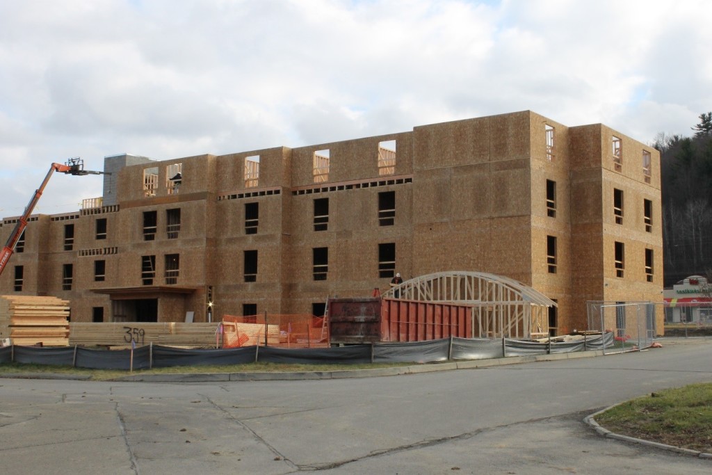 NK BHANDARI recently completed the structural engineering for a new 4 story hotel in the Southern Tier region of New York. The hospitality market is very competitive and initial cost can be the deciding factor for long-term viability of a hotel development project. For this building, a system of wood bearing walls and open-web wood floor trusses was selected. The wood systems have a lower initial cost than other options and the open webs of the floor members allow both the structure and the mechanicals to occupy the interstitial space thereby reducing the floor to floor elevations and the overall height of the building.
Weather can be a serious hindrance to the construction industry in this region of New York – especially in the late fall and early winter, so the contractor elected to further optimize the construction by panelizing the walls. With a panelized system, the walls are all constructed in the controlled environment of an offsite factory then shipped in 10 to 12 foot sections and erected on site. This allows for the building to quickly get built and enclosed. The longer duration of the field “stick-built” method is substantially reduced, and the length of time the wood members are exposed to the elements is therefore also reduced which helps eliminate delaminated floor sheathing issues often associated with traditional wood construction.
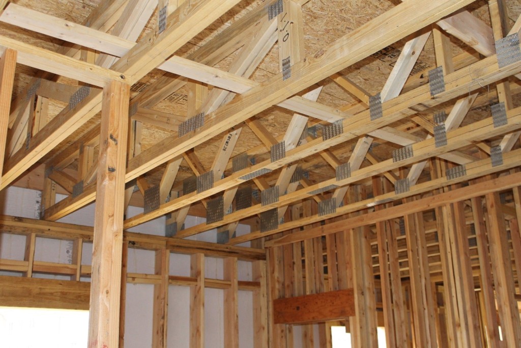 The economy of metal-plate-connected wood trussed roofs is widely recognized, and are often used even if the structure is concrete block. For a wood building like this, wood trusses are the go-to solution. This building explores the versatility of the system with traditional gables and custom round-arched dormers integrated to produce the architectural aesthetic required.
A similar approach could be achieved with cold formed steel bearing walls and trusses if a non-combustible system is desired.