

So you have something valuable in your building that you want to protect, like children at a daycare or the entrance to a federal building, yet you want to be able to enjoy the beautiful sunshine and views of the outdoors, what do you do? Thankfully, there are decades of research and many manufactures out there that are able to provide you with products that can provide you a security solution for such a case.
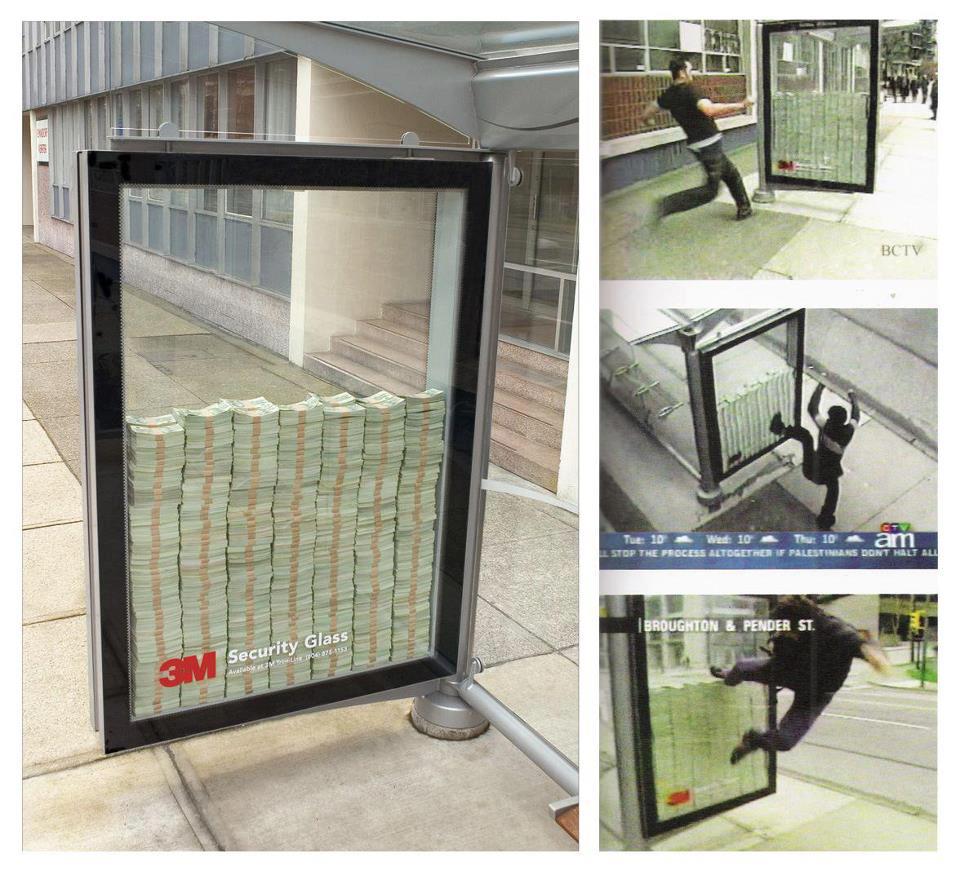 Figure 1: 3M put money inside a bus stop partition in Vancouver, Canada to prove their security glass could withstand nearly any attack by an unarmed person. If anyone could break the glass, they got the money. No one broke the glass.
To tackle this problem, the first real question you have to ask is “what am I protecting against?” Are you trying to protect against a guy with a hammer breaking through your window, an active shooter, falling ice. The gamut is nearly limitless but needs to be defined early on in the decisions making process. Until you narrow that down, the options, and cost, are boundless. If you are trying to stop a burglar, that can be accomplished without too much trouble. If you are trying to stop an active shooter, or are looking for “blast protection”, things get complicated quickly.
The chart below lays out the major categories of protected glazing and potential materials that will accomplish that: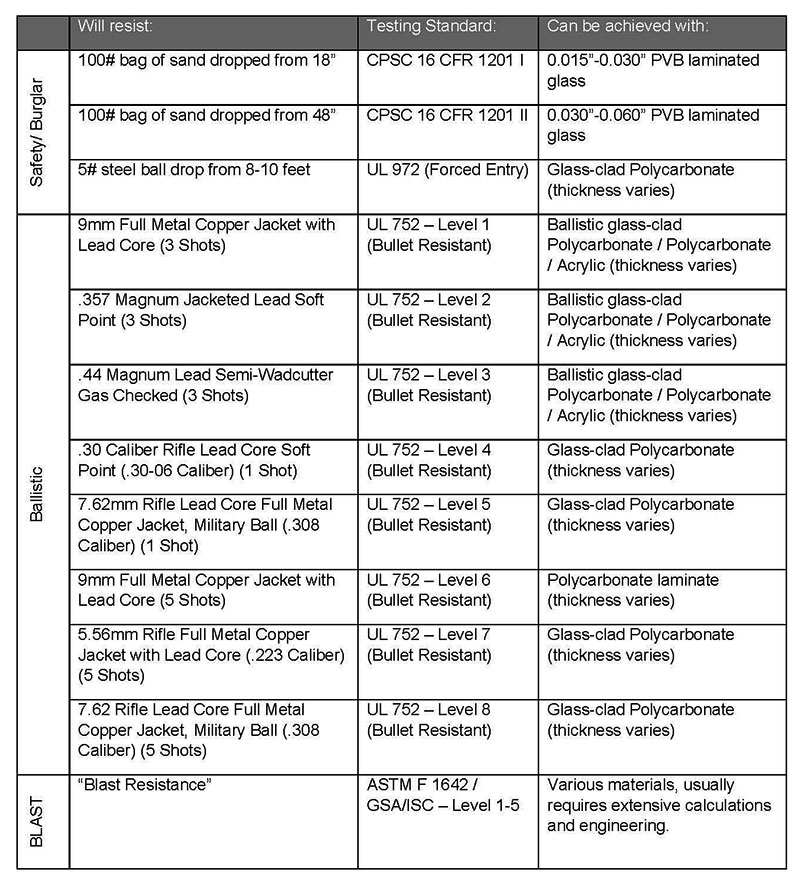 Now if that table with all of those options looks confusing, it is. The worst part is that depending on manufacturer, one might make a glass-clad polycarbonate that is UL 752 level 3 rated that is ½” thick, where another might make the same apparent product that is ¾” thick. So how do you choose? It all comes down to what you are trying to protect against, and how important the aesthetic is. Even though many products pass the specific UL or ASTM testing requirements, they often vary in thickness, color, and physical make up and thus may not be suitable depending on the application.
Once a decision is made on what level of security you want and what type of material you want, you then have to struggle with how to secure this very expensive, but very dependable piece of glazing into place. Depending on the material and the manufacturer, you can use a captured system like a storefront or curtainwall system, you can use a custom designed steel framing system with glazing channels, or you might even be able to use mechanical fasteners to anchor through the material depending on its composition. The real factor in choosing the right framing system is the frame’s ability to withstand the kinetic energy distributed to it by the burglar / bullet / blast. Selecting the right frame typically requires engineering calculations and/or consulting a specific manufacturer to select a pre-engineered system.
If all of this sounds rather complicated, it’s because it is. NKB has done multiple projects where the design necessitated that some form of transparent security be provided, and each time we go through answering all of these questions in order to choose the right solution. Transparent security is a building component that requires special attention to detail and to ensure the right outcome. Do not just pick a product off the shelf when dealing with such complex problems, consult a design professional; broken glass in this case is a lot more dangerous than just a sharp edge.
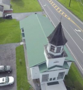
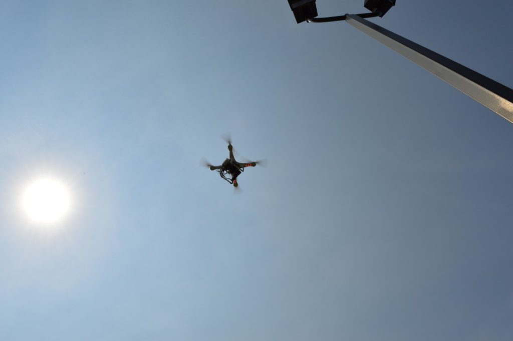
Aerial Image taken with NKB’s UAV
Documenting existing conditions can often times be difficult for Architects & Engineers, because the conditions are concealed, too high, out of reach, or outright unsafe to get to. The question is, how can you see things that you cannot ordinarily see? Technology. Using technology to your advantage is the way you get the job done.
When posed with performing a condition assessment and preparing the design for the restoration of the steeple on the historic St. Mary’s Anglican Church in Liverpool, NY, NKB offered the use of our unmanned aerial vehicle (UAV) with an onboard high definition digital camera to document the conditions that were otherwise unobservable from the ground. The conditions were too high and unsafe to try to get to with a ladder or lift. By using our UAV, NKB could provide high definition still or video imagery of conditions on the steeple that the owner, design professional, and contractor could not otherwise see. Having this visual documentation of an otherwise obscured condition is allowing the design team and the contractor to proceed with the design and construction activities on the steeple in an orderly manner.
The next big thing in Architecture and Engineering is not necessarily some earth-shaking new approach to re-invent the built environment. The next big thing is how we as design professionals can use technology in creative ways to provide unparalleled service for our clients.
Using technology in creative ways to work for you.
Aerial Image taken with NKB’s UAV
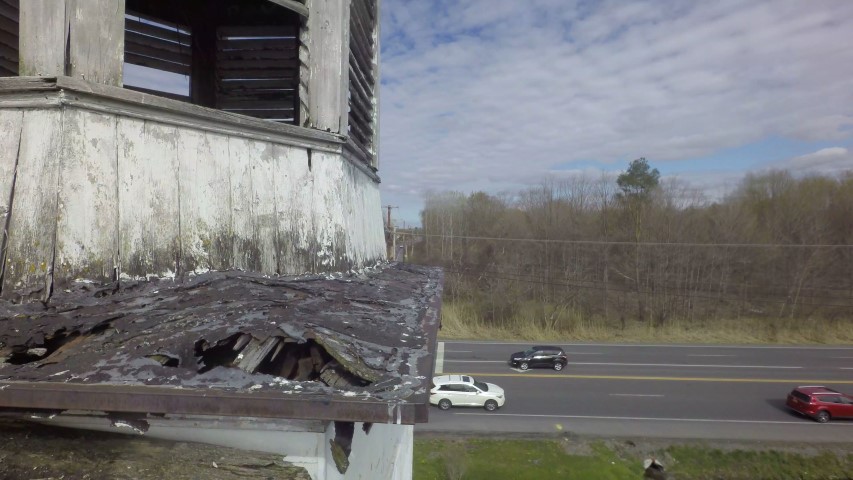
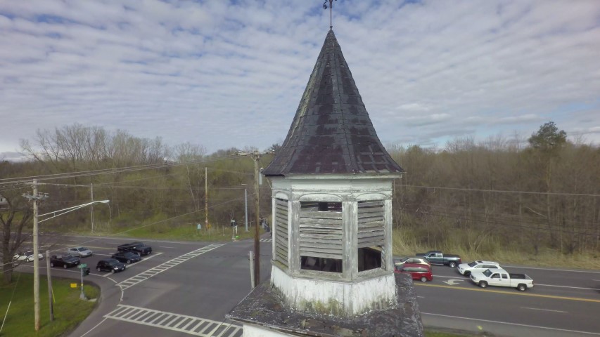
Up close on a hard to reach spot using NKB’s UAV
Recently, NKB was called by an existing client to assist them with a problem they began experiencing with ice falling from window sills several stories above the ground. In mid-January, Old Man Winter comes to Upstate New York and dropped 14 inches of snow in about 36 hours. Temperatures ranged from 15ºF to 25ºF and wind speeds were consistently between 5 and 15 mph with occasional gusts of up to 35-40mph. Over the two days which followed the completion of the storm there were reports of ice buildup and falling to grade below. The client called us in to examine what might be causing the ice build-up. What we found when we walked the perimeter of the building and looked out on various façades of the building from facing windows was very telling.
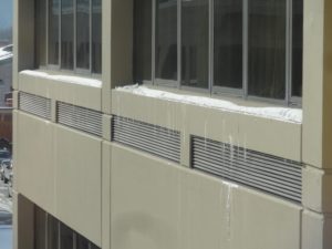
Melting at Window Sills
Each window sill showed some snow and ice still in place near the edge of the sill. The 6-8 inches nearest to the window was clear in all locations. Every – Single – Window. All 245 instances, showed the same clear area adjacent to the windows with ice buildup at the edge. Our client admitted that they did not recall if this was a problem prior to the façade renovation project. It had been several years since pedestrians were allowed anywhere near the building so there was no institutional memory of occurrences like this happening previously.
We began running through the list of things that could possibly cause this melting condition:
1. The windows are known to be headaches to the building management. Infiltration problems are known to exist so could we be getting warm air leakage at the windows causing snow melt? Well, warm air leakage would likely be a less uniform condition. Coupled with the fact that the façade renovation project that was just completed included the resealing of the entire perimeter of each of the windows, we decided that this was not a major contributor.
2. Since this is a horizontal surface, it could be that the sun was causing the snow melt, right? When we noticed that the condition existed at all faces, regardless of orientation (including the north facing façade which gets essentially zero sun at this time of year), we ruled out solar melting as a primary contributor to the problem.
3. Upon a closer inspection of the window sills and a reexamination of the original construction documents from the 1970’s, we realized that this pre-cast concrete window sill was likely acting as a thermal short. It extended, unbroken, from the exterior to the interior of the building.
A thermal short is a condition in which thermal energy is allowed to flow along a path of least resistance from a heat source to a colder region on the other side of the barrier. Consider an electrical short circuit. An electrical short is one in which the electricity is allowed to flow along a shorter path than intended and in doing so damages components and ceases to work properly (hopefully without killing anyone in the process). A thermal short is a similar phenomenon. In most homes the walls contain some form of insulation to provide greater resistance to heat loss in the winter or air conditioning in the summer. In a commercial building, a thermal short is most often exterior panels supported by metal clips and brackets which are tied to metal structural components. This string of metal tied to metal creates an easy path along which thermal energy can flow. This building did not have an unbroken string of metal from exterior to interior making identification of a thermal short in this case particularly difficult. However, the uninsulated concrete still served the function of a thermal short by acting as a path of least resistance for the thermal energy in the building to escape.
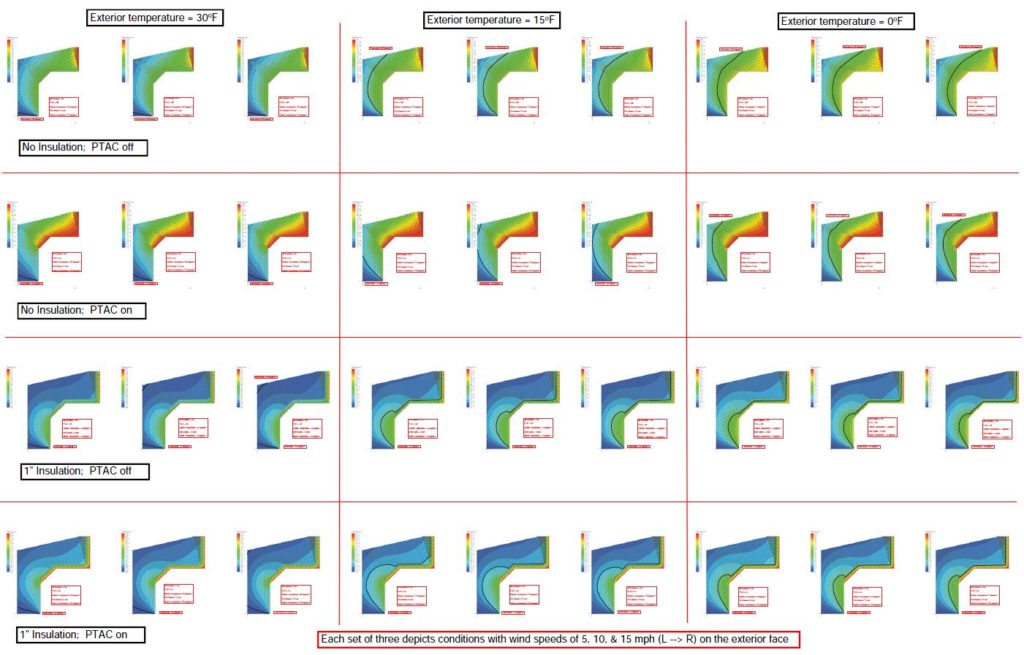
Most people consider concrete to be of sufficient thermal mass and to be a relatively capable thermal insulator. Compared to metal window frames and door frames or z-channel, this understanding is exactly right. Compared to air gaps and closed-cell insulation, this is an error in judgement. In an effort to better explain what was causing the observed conditions and to predict a likely solution we put together, a Finite Element Analysis (FEA) thermal model of the window sill conditions. We created 50 different runs with a varying set of boundary conditions and thermal loads. These runs examined the following conditions:
| Variable | Values |
| Insulation in PTAC cavity | Yes/No |
| PTAC operational | Yes/No |
| Exterior Temperature | 30º/15º/0º F |
| Wind Speed Across Face of Building | 5/10/15 mph |
What came out of the simulations was both expected and surprising at the same time. The results of the model with the existing conditions as inputs produced outputs which would predict the melting and refreezing conditions exactly as observed.
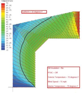 Existing condition |
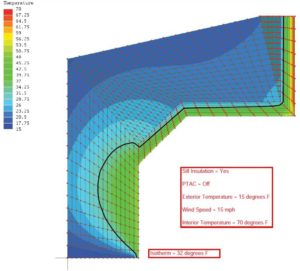 Proposed condition |
We then created a series of simulations in which we insulated the interior faces of the concrete so as to attempt to create the thermal break required to prevent the wholesale loss of building heat through the concrete sill. The results of these simulations predict that 1 inch of polyisocyanurate insulation on the interior face of the concrete sill will prevent melting on the sill in all conditions except those which also do not allow the snow melt to refreeze on the concrete.
Over the remaining winter months, we have found that this condition seemed to be limited to larger snow events. We had several smaller snow falls (less than 4 inches at a time) and it seems that there is a critical mass of snow which is required to create the pieces of ice that are large enough to separate from the building. This critical mass has not been reached since that snow storm in mid-January but considering that we, in Syracuse, routinely win the Golden Snowball award for largest snowfall total during the winter months, we can be assured that we will typically get at least one storm capable of creating the conditions to cause this occurrence each year. The implementation of the findings of this analysis is yet to be completed and will be the topic of ongoing discussion with the client.
So what is the moral of this story? Thermal energy is a slippery devil. It finds unexpected paths and causes unexpected consequences. Thermal shorts in all of their forms can be a significant building performance and energy consumption issue. These issues impact not only the long term performance of the building itself, but the people who use the building day-in-and-day-out. This case study serves to highlight the usefulness of a relatively straight-forward Finite Element Analysis steady state thermal model in helping to determine the causes of a given condition as well as helping to identify what recommendations we can make in order to best address them.
N.K. BHANDARI is pleased to announce it has recently received the Federal Aviation Administration (FAA) Certificate of Waiver or Authorization (COA) and a Section 333 Grant of Exemption allowing the firm complete use of Unmanned Aerial Vehicles (UAV’s) for commercial use. This added capability allows NKB to provide an expanded set of services to our clients while also ensuring greater safety for the public, our clients, and our employees.
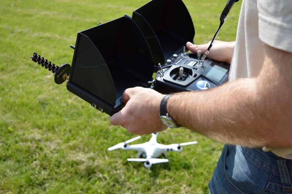
Through the use of our UAV technology, we are able to perform visual inspections of various types for structures including building facades, roofs, towers, bridges in both high definition still images, and 4K video in both the visual and infrared spectrums. Utilizing our DJI Phantom quad-copter UAV and automatic waypoint navigation, we are also able to provide terrain mapping services through photogrammetry. These technologies provide us with a set of files which can be utilized in our design platform software to create existing condition drawings and to obtain a topographical representation of any property with greater ease than was previously possible.
At N.K. BHANDARI, we embrace the use of technology to deliver a higher level of service as Architects and Engineers. By welcoming this technology, we are positioning ourselves at the leading edge of the design community. Through compliance with current FAA regulations relating to the usage of UAV’s we are able to provide a heightened level of peace of mind for our clients. All of our clients know that NKB not only works within the existing regulatory framework, but we also maintain all required insurances and operator training to ensure the highest level of client, employee, operator, and most importantly, public safety during our UAV operations.
NKB is excited to continue to lead by example by embracing and utilizing leading edge technology such as unmanned aerial vehicles with visual and infrared sensors to deliver unique results through unrivaled service.
If you are reading this you might be asking yourself, “Self, how do I capture meaningful data with my infrared camera?” Or, “Self, do I know enough of the basics of thermography in order to perform a thermal analysis?” Or, “Self, why in the world are you speaking in the third person?” In the world of thermography there are many considerations that must be made when taking and analyzing the images captured but there is one piece of science that is most important in obtaining meaningful results. This is especially true if your goal is to take even remotely accurate temperature readings using your IR camera. This little nugget of thermographic gold is:
Energy Absorbed + Energy Reflected + Energy Transmitted = Total Energy Observed from a Body
OR
α + ρ + τ = 1
where:
α= Ratio of Energy Absorbed by a Body to Total Energy Observed from a Body
ρ = Ratio of Energy Reflected by a Body to Total Energy Observed from a Body
τ = Ratio of Energy Transmitted by a Body to Total Energy Observed from a Body
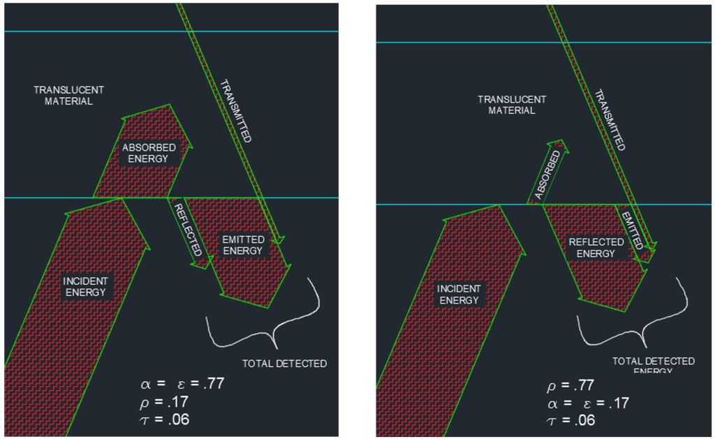
Translucent Material, Highly Absorptive vs. Translucent Material, Highly Reflective
Bear with me while I lay out a couple of necessary concepts. For most opaque materials, the transmitted energy is equal to zero. Even my children can grasp this concept when I explain to them that we don’t typically feel the warmth of the sun directly while standing in the shade. We feel the temperature of the air around us. The infrared energy is not able to penetrate most opaque objects so this concept is somewhat intuitive. The implication of this fact is that for most objects which appear in an IR image, the transmittance can be taken to be zero. Additionally, in the mid-1800’s, Gustav Kirchoff gave us a relationship that came to be known as Kirchoff’s Law of Thermal Radiation. I will significantly simplify Kirchoff by telling you that his Law of Thermal Radiation states that, for a body at thermodynamic equilibrium (constant temperature), the absorptivity is equal to the emissivity (α = ε).

Pasta Sauce on Stove – Delicious!
Simply put, whatever thermal energy the object absorbs, it also radiates that same amount back to the atmosphere. If the absorptivity and emissivity were different the object would be in the midst of a temperature change. Think of a pot of tomato sauce with the lid on left to simmer on a stove. The temperature of the pot is hot enough to burn you if you touch it but it has reached a constant temperature and is no longer getting any hotter. The energy absorbed from the burner by the pot (absorptivity) is equal to the energy emitted to the atmosphere by the pot (emissivity).
So, we can simplify and restate our previously identified relationship to be:
ε + ρ =1
where:
ε = Ratio of Energy Emitted by a Body to Total Energy Observed from a Body
ρ = Ratio of Energy Reflected by a Body to Total Energy Observed from a Body
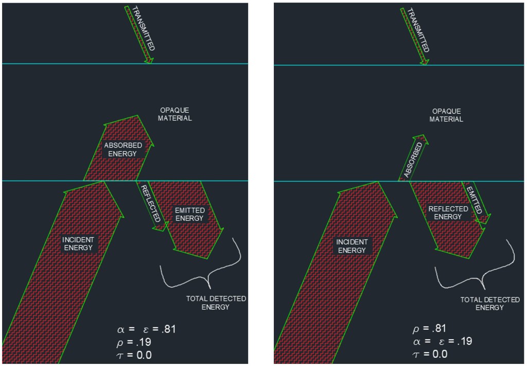
Opaque Material, Highly Absorptive vs. Opaque Material, Highly Reflective
How about a couple of real life images to illustrate this?We can now see an inverse relationship between the thermal reflectance and the thermal emissivity of an object. The more reflective something is, less of the energy that we see come from its surface is actually emitted by that object.
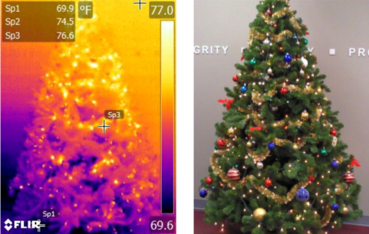
IR & Visual Images of Christmas Tree
In the image above we see a traditional Christmas tree and the corresponding thermal image. In this image we can clearly see a thermal gradient from floor to ceiling as is to be expected. We also, unsurprisingly, see bright spots where the lights are emitting additional heat being picked up by the IR camera. This is a good example of looking at the thermal energy being emitted by what are mostly opaque, highly emissive objects. Now let’s take a closer look…
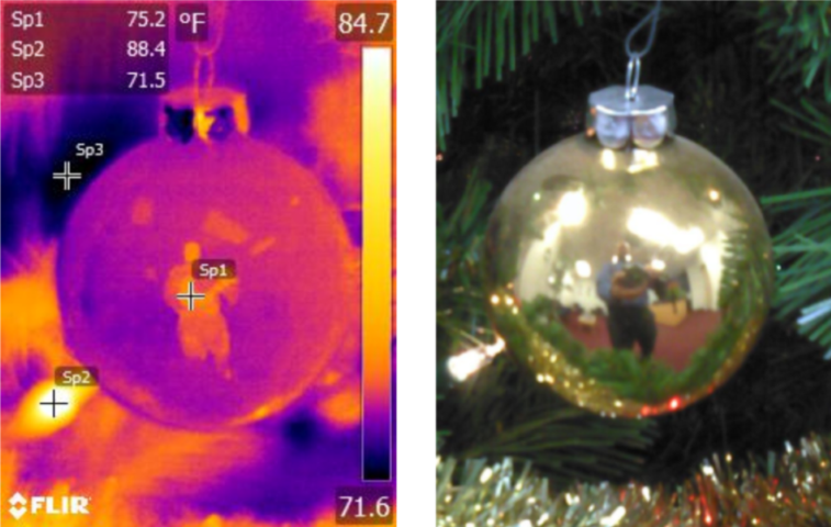
IR and Visual Images of Ornament
In the above image we are looking at one of the ornaments on the tree shown in the previous image. We can see that it is highly reflective in the visual spectrum. When we look at the IR image, sure enough, there is a reflection of the person taking the picture here as well. The temperature shown on the ornament is going to be rather inaccurate because it is actually measuring a portion of the photographer’s heat energy. This image demonstrates the difficulty we can experience when taking IR images without regard to the nature of the object we are documenting. We must have an understanding of what the material and finish is of the object we are analyzing in the IR images.
What is the bottom line to all of this? Just because your IR camera says that the temperature is 106.5oF, doesn’t mean that it is. When we look at an object with a highly reflective surface we may be picking up a portion of the IR energy of other sources in the area. If we are looking at something that may be translucent to IR wavelengths, we may be seeing the IR energy of objects behind what we are attempting to measure. In order to obtain meaningful results from our IR images we must account for these factors (and many, many others – but those are for later posts!). Be sure to stop by often to stay up to date on our series of building science posts. Some of our future topics will include: The Primary Concerns of Thermal Image Capture – FORD, Accounting for Environment Interference in Thermal Images, Envelope U-value and Moisture Migration, The Wonder of Thermal Hysteresis, and much, much more! If there are other topics that you would like to see us cover, feel free to contact us and let us know.